
A residential septic system needs more than a tank location on a site plan. For this Melbourne Beach project, CivilDraft prepared the complete submission package, bringing together the site layout, treatment-system documentation, chamber drainfield coordination, septic tank details and supporting design calculations.
The project documentation addressed a performance-based onsite sewage treatment and disposal system (PBOSTS) concept using a FujiClean CEN5 aerobic treatment unit and a chamber-style drainfield. The work connected the wastewater design information with the proposed home and the constraints recorded in the supplied site documents.
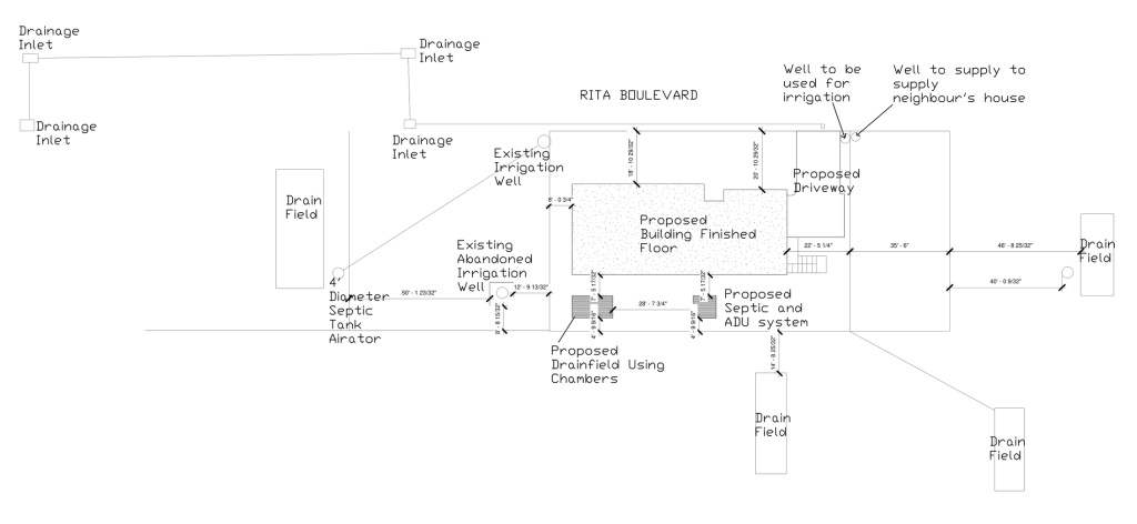
Septic site planning around existing wells and drainage
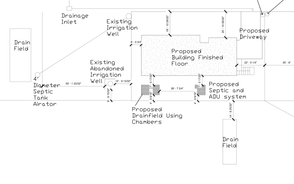
The supplied site information showed several features that mattered to the layout: the proposed building and driveway, existing and abandoned irrigation wells, a neighbouring water-supply well, drainage inlets and nearby drainfield locations. Those relationships needed to remain visible in the drawing set rather than being reduced to a diagram of the new system alone.
CivilDraft developed the site documentation around that information, identifying the proposed wastewater treatment location and chamber drainfield arrangement alongside the building. Dimensions and callouts provided a common reference for reviewing the layout against the available survey and site-evaluation records.
The distinction between irrigation wells, abandoned wells and a potable-water supply was an important coordination issue. The package brought those recorded features into the site-planning discussion; the reviewing authority determines the applicable requirements and accepts the final design.
FujiClean CEN5 and chamber drainfield coordination
The treatment concept paired a FujiClean CEN5 aerobic treatment unit (ATU) with a chamber-style drainfield. Documenting that system required coordination between the building sewer, treatment-unit position, drainfield location, access and the manufacturer information supplied for the project.
The calculation package addressed the residential wastewater-flow basis, treatment-capacity verification, soil-loading assumptions and absorption-area calculations. It also addressed the relationship between the absorption-area elevation and the estimated seasonal high water table. These are separate checks: a tank’s storage volume is not its daily treatment rating, and a footprint on a plan does not establish acceptable vertical separation.
Wastewater flow and groundwater information
The project calculation record uses a residential flow basis of 300 gallons per day and records an estimated wet-season water table 26 inches below existing grade from the historical site evaluation. These property-specific inputs informed the calculation work; they are not general design allowances for other Florida properties.
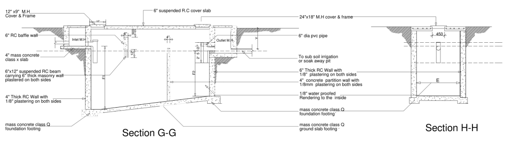
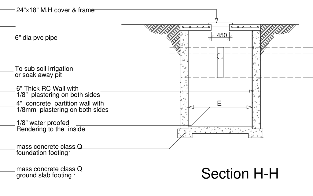
Septic tank plans, sections and construction details
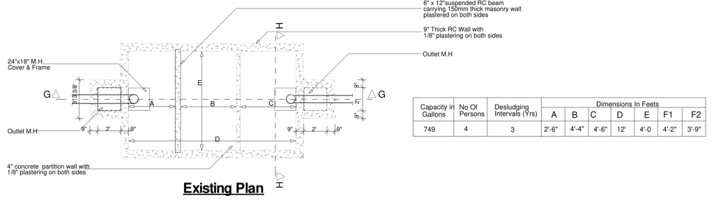
The drawing files also document tank detailing in plan and section. Access openings, internal divisions, baffles, pipe connections, cover slabs, walls and the base are shown together so the tank arrangement can be read across multiple views.
The tank-detail drawings below are part of the project documentation. They are presented separately from the FujiClean manufacturer drawings, which provide the product-specific information for the proprietary treatment unit.
What CivilDraft delivered
- Site-layout documentation: the proposed residence, wastewater system and surrounding features brought into a coordinated drawing.
- Treatment-system documentation: CEN5 ATU and chamber drainfield coordination supported by the supplied manufacturer information.
- Septic tank drafting: plans, sections, access arrangements, baffles, pipe connections and construction-detail annotations.
- Supporting calculations: the wastewater-flow basis, soil-loading and absorption-area methodology, water-table considerations and setback review framework.
- Submission notes: installation, access, pipe-level coordination, system protection, startup and maintenance considerations.
- Document coordination: the client’s instructions, survey, historical site-evaluation information and equipment references organised into the complete package.
Project status: submitted for review
CivilDraft completed and submitted the package. This case study records the design and documentation scope at submission; approval and construction are separate project milestones.
The documented review scope allowed one consolidated response to health-department comments where the original project scope and design basis remained unchanged.
Historical permit and site-evaluation records informed the work but were not treated as approval of a new system. Survey and manufacturer information remained supporting documents from their respective authors.
Planning a residential septic system in Florida?
Send your property location, survey, proposed floor plan or bedroom schedule, and any available soil or site-evaluation records. If you already have review comments, include the complete correction letter and the drawing set it refers to.
We will review the available information, define the drafting and calculation scope, and confirm the fee and production schedule. Where a project requires licensed professional review or a seal, that work is coordinated with collaborating licensed professionals.
Request a septic design quote Email your project files
Project drawings are shown for portfolio use. They are not instructions for construction or reuse at another property.