
CivilDraft prepared the complete septic package for a residential addition in North Miami Beach, Florida. The documentation coordinated a Norweco Singulair Green treatment unit, a separate dosing/pump tank and a subsurface drainfield with the proposed two-story addition and the surrounding site features.
The work brought together the wastewater layout, treatment-system details, project installation notes and the supporting survey, architectural and percolation information. The design stage is complete; this case study describes the documentation prepared without presenting it as a permit-approval or construction record.
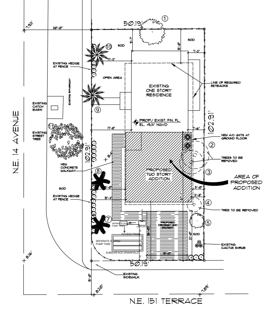
Septic site planning for the residential addition
The site documents show an existing one-story residence and a proposed two-story addition. The wastewater layout needed to be read alongside the proposed building footprint, deck and walkway, existing sidewalk, catch basin, paving, landscaping and property boundaries.
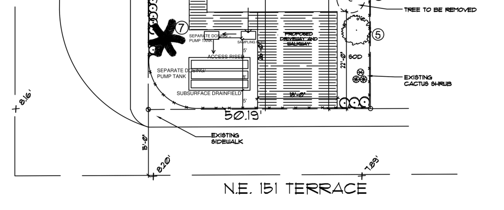
The septic layout identifies the separate dosing/pump tank, sampling port, access riser and subsurface drainfield. Dimension callouts give the project team a common reference for coordinating these components with the addition and exterior works.
The package used the supplied boundary survey and architectural site and floor plans as supporting inputs. The survey and architectural design remained the work of their respective authors; CivilDraft’s scope was the complete septic documentation package.
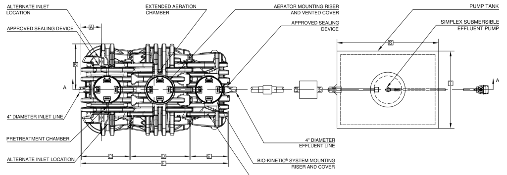
Norweco Singulair Green treatment and subsurface disposal
The treatment documentation identifies the Norweco Singulair Green Model 960 family and shows a separate dosing/pump tank downstream of the treatment unit. The project notes set out a wastewater route that connects treatment, sampling, pumping and subsurface disposal.
- Building sewerConveys wastewater from the residence.
- PBTS treatment unitProvides the documented treatment stage.
- Sampling portProvides the documented sampling point.
- Dosing/pump tankHolds the effluent pump and controls.
- Subsurface drainfieldReceives flow through the pressure line.
The project-specific notes are important here. Although the manufacturer’s standard drawing includes spray components, this project’s documented disposal route is a subsurface drainfield. Spray irrigation is excluded unless separately approved. The case study therefore describes the site-specific arrangement rather than treating every component on the standard equipment drawing as part of the project.
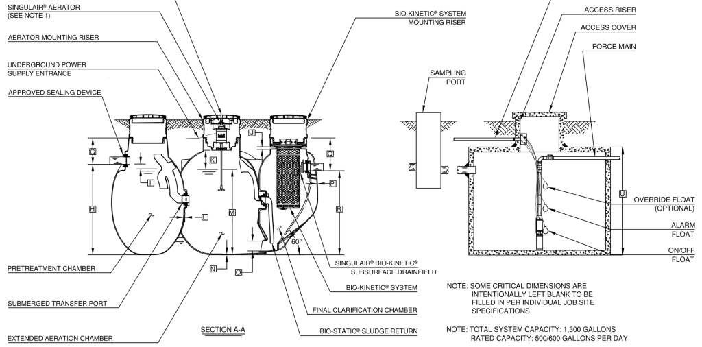
Coordinating the pump tank, piping and service access
The installation notes identify a 4-inch PVC gravity building sewer unless otherwise noted, followed by the treatment unit, sampling point, dosing/pump tank and pressure line. The tank details show the pump, operating and alarm floats, access risers and the electrical conduit to the control panel.
The documentation also addresses dedicated electrical service and controls, access covers at finished grade, field verification of inverts and dimensions, and coordination with utilities and nearby site features. Equipment and hydraulic details are to be read together with the final project requirements rather than inferred from a generic tank diagram alone.
Percolation and site-investigation inputs
A percolation and subsurface-investigation report by Dynatech Engineering Corp. was supplied for the property. Its testing and groundwater observations formed supporting site information for the wastewater work. They were not represented as testing performed by CivilDraft.
The project notes identify final wastewater flow, tank capacity, pump selection and drainfield sizing as design and jurisdictional coordination items. The equipment drawing’s stated capacity is not used here as a substitute for the residential design flow, and a field groundwater observation is not presented as a verified seasonal high-water level.
Complete septic-package scope
- Wastewater site layout: treatment, sampling, dosing/pumping and drainfield locations coordinated with the proposed addition.
- Treatment and tank documentation: project plans and sections showing the equipment arrangement, pipe connections and access.
- Installation notes: gravity and pressure piping, electrical service, controls, covers and field-verification requirements.
- Supporting-document coordination: survey, architectural drawings, percolation report and manufacturer information brought into the septic package.
- Professional-review inputs: coordination of the engineer-signed septic drawing supplied in the project records.
Project status: design completed
The complete septic design package was prepared. The confirmed milestone for this case study is completion of the design work; submission, permit approval and construction are separate milestones.
Planning a septic system for a Florida home addition?
Send your project location, existing survey, proposed addition plans and any available soil or percolation information. If an authority has already reviewed the project, include the complete comment letter and the drawings it refers to.
We will assess the documentation scope and confirm the required inputs, fee and production schedule. Where required, licensed professional review and seals are coordinated with collaborating licensed professionals.
Request a septic design quote Email your project files
Septic and wastewater design services · Florida drafting services · More project case studies
Drawing credits: architectural site-plan background, J. Bonfill & Associates, Inc.; equipment reference geometry, Norweco; survey and field-testing inputs, their respective authors. Project drawings are shown for portfolio use and are not instructions for construction or reuse at another property.