
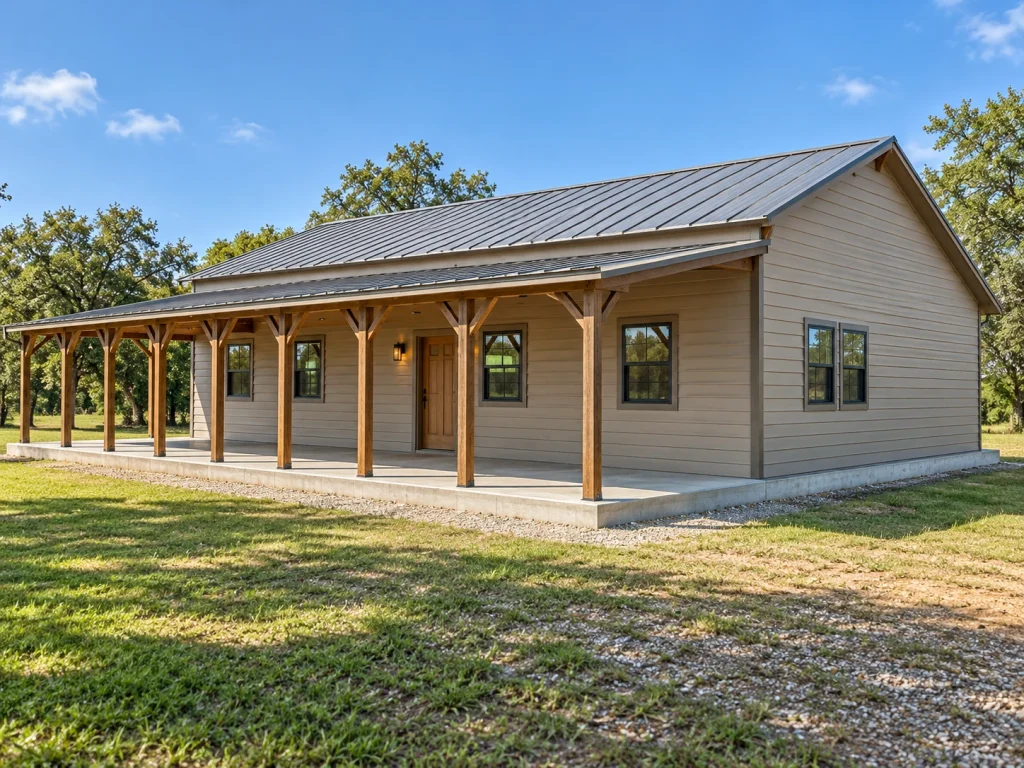
CivilDraft prepared the complete documentation package for a two-bedroom home in North Carolina, bringing architectural planning, steel and timber framing, MEP coordination, modeling and material takeoff into one project record.
The design combines a gable-roofed residential unit with a covered lean-to porch. The work progresses from exterior visualizations and room planning to foundation drawings, framing views, building sections, service layouts and a CostX material schedule.
Two-bedroom planning and exterior design
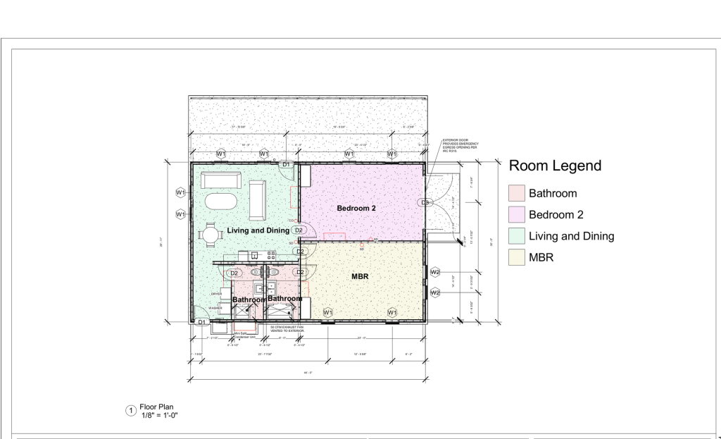
The floor plan organizes two bedrooms, two bathrooms and a shared living/dining area, with doors, windows and service locations documented around the room layout. The covered porch creates a separate outdoor zone along the building frontage.
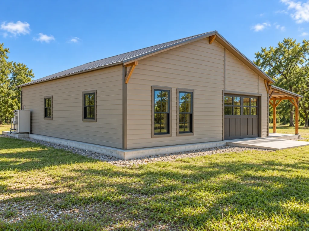
Elevations and exterior visualizations communicate the gable roof, porch posts and bracing, window placement and large glazed opening. These images explain the design intent; they are labelled as visualizations rather than photographs of a completed building.
Steel-frame and timber wall-framing documentation
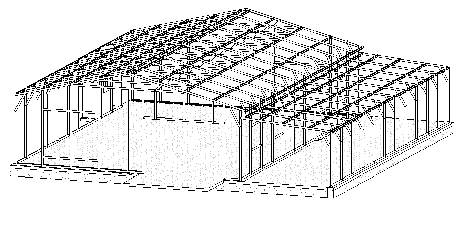
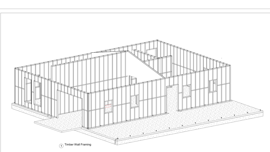
The structural drawing set separates the steel building frame from the timber wall-framing layout. Three-dimensional views make the relationship between the slab, main frame, internal partitions and porch structure easier to follow before reviewing the individual plans and sections.
The steel model shows columns, roof members and bracing, while the timber model records wall positions and openings. The wall-framing sheets develop those views into dimensioned layouts and assembly details, including the interface between metal cladding, framing, insulation and internal linings.
Foundation, roof and building-section coordination
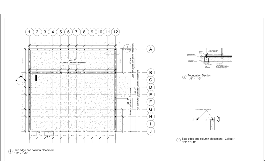
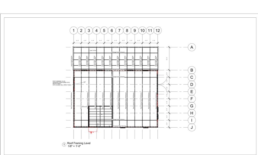
The foundation sheets document slab-edge geometry, column positions and base/anchor details. Roof-framing drawings relate the main building frame to the lean-to porch, while the building sections communicate levels, roof form, openings and internal construction relationships.
The package also includes individual wall-framing elevations and a door/window legend. Those views connect opening locations and vertical dimensions with the floor plan instead of leaving the reader to infer them from a single model image.
Electrical, plumbing and HVAC drawings
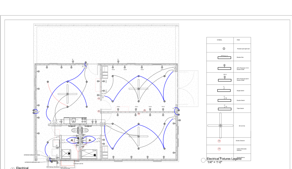
The electrical and power plan records lighting, switching, outlets, panel locations and equipment connections using a drawing legend. Project notes address detector locations, bathroom exhaust and generator-transfer coordination.
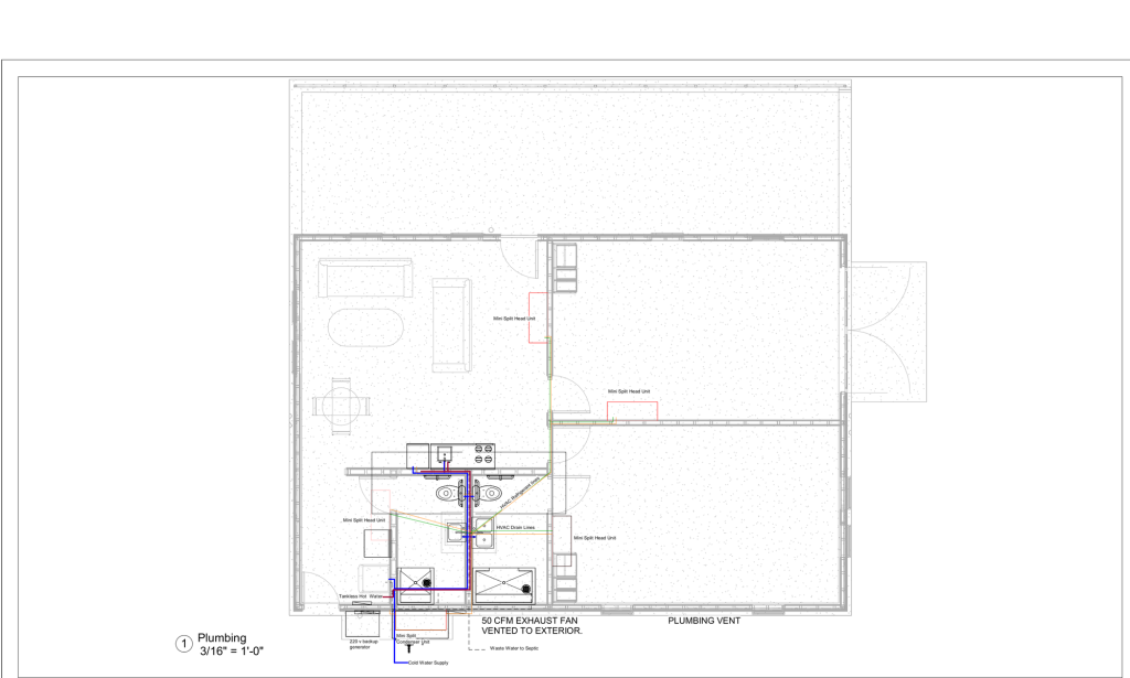
The plumbing and HVAC drawing brings together cold-water supply, hot-water service, wastewater routing, mini-split equipment, refrigerant lines and condensate drainage. Coordinating these routes with the room layout makes their relationship to bathrooms, fixtures and equipment locations visible in the drawing set.
The case study describes the documented layouts. It does not present a drawn mini-split arrangement as a verified heating/cooling load calculation or an equipment-capacity certification.
CostX material takeoff
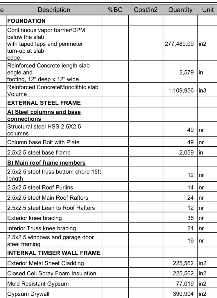
The project material list was prepared in iTWO CostX. It groups measured quantities for the slab and footing, steel columns and roof members, timber framing, cladding, insulation, linings, openings and service items.
The schedule gives the project team a basis for reviewing material requirements and discussing procurement. Quantities need to be reconciled with the drawing revision being used for purchasing, and project pricing requires agreed rates. The supplied report records quantities without a priced construction total.
Complete-package deliverables
- Architectural documentation: floor plan, elevations, sections and door/window legend.
- Framing and foundation drawings: steel frame, timber wall layouts, slab/column placement, ceiling and roof framing.
- MEP coordination: electrical/power layout and plumbing/HVAC service documentation.
- Design communication: exterior visualizations and three-dimensional model views.
- Quantity takeoff: CostX material descriptions, measurements and units.
Project status: design completed
CivilDraft’s complete design documentation scope is finished. The confirmed stage is design completion; this case study does not claim permit approval or completed construction. The supplied realistic exterior images are visualizations.
Need coordinated drawings for a residential project?
Send your location, project brief, site information and any existing sketches or plans. Tell us whether you need architectural drafting, framing documentation, MEP coordination, modeling, material takeoff or a combined package. We will define the scope and required inputs before confirming a fee and schedule.
Where a jurisdiction requires licensed professional review or a seal, that work is coordinated with collaborating licensed professionals.
Discuss your residential project Email your project files
Architectural and CAD drafting · MEP drafting and coordination · Quantity surveying and takeoff · All projects
Project drawings are displayed for portfolio use and are not construction instructions or documents for reuse at another site.